Creating Your Own Voltmeter and Ammeter from Scratch
Written on
Understanding the Basics of a Galvanometer
You might be surprised to learn that you can easily find an affordable digital multimeter that can measure voltage, current, and resistance. However, why not embark on a DIY project and create your own device? It can be a rewarding experience!
The first project involves building an ammeter and voltmeter utilizing a galvanometer (see image below). A galvanometer consists of a wire coil that rotates in a magnetic field. When electric current flows through the coil, it generates a magnetic field that interacts with the surrounding magnet, causing the needle to move. Essentially, the needle's movement indicates the amount of electric current passing through it.
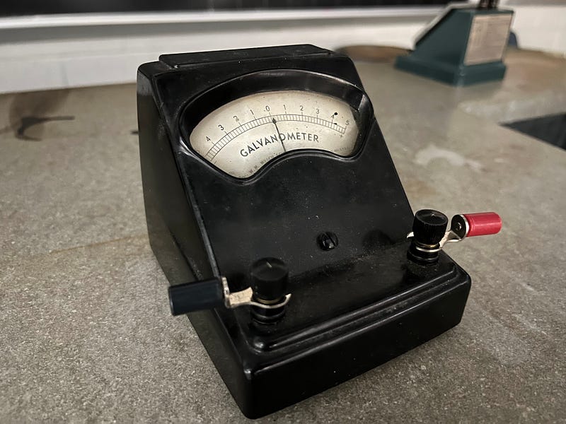
Despite its functionality, there are a couple of challenges. Firstly, the scale lacks defined units, merely ranging from -5 to +5. Secondly, even a small current can push the needle beyond the +5 mark. Thus, modifications are necessary to accurately measure current and voltage.
Finding the Maximum Current and Resistance
Before constructing the ammeter, it’s crucial to determine specific properties of the galvanometer. How do the tick marks correspond to actual current? What is the maximum current that results in a reading of 5?
To find out, I’ll run current through the galvanometer while simultaneously measuring it with a known ammeter. This allows for accurate comparison, although the galvanometer's maximum current rating is quite low.
Here's a visual of the setup I used:
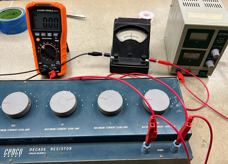
In this configuration, the galvanometer is connected in series with a digital multimeter and a low-value resistor from a decade resistance box.
The circuit schematic is as follows:
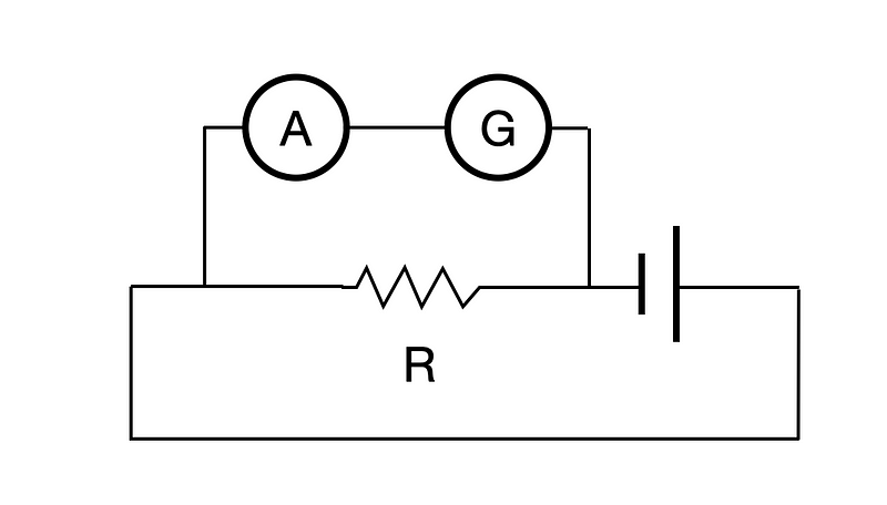
By using a low resistance in parallel with the meters, most of the current bypasses the galvanometer, allowing for small current measurements. As I varied the resistance, I was able to chart current against galvanometer readings.
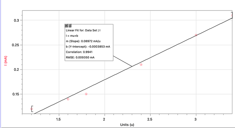
From this graph, four key insights emerged:
- The data shows a linear relationship between actual current and the galvanometer reading.
- The slope of the line indicates that each milliampere corresponds to approximately 0.0897 units.
- The maximum current correlating to a 5 unit reading is about 0.44 mA.
- The y-intercept is slightly off zero at -0.00039 mA, but it’s negligible for practical purposes.
Next, I need to determine the resistance of the galvanometer coils. Though I could have measured both current and voltage simultaneously, I opted to connect a multimeter in resistance mode instead.
This method is quite effective. When the digital multimeter measures the galvanometer's resistance, it inadvertently allows a tiny current to flow, showcasing how the multimeter operates.
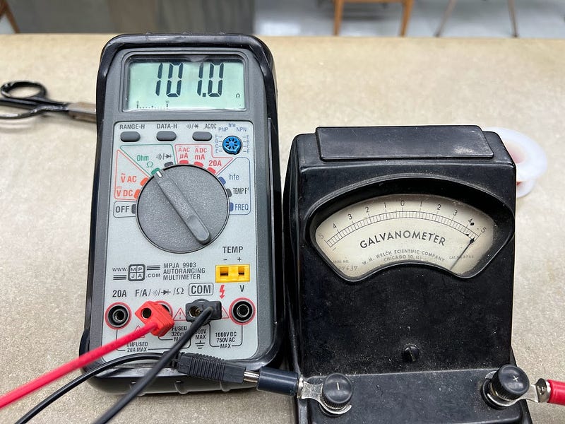
This particular galvanometer exhibits a resistance of 101 Ω.
Building an Ammeter
The galvanometer can only handle up to 55 mA. To extend its capability to 200 mA, a shunt resistor is required. This resistor, placed in parallel with the galvanometer, enables most of the current to bypass it.
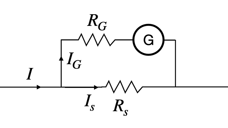
Here, the galvanometer is depicted alongside its internal resistance (R_G) and the shunt resistor (R_s). By applying the voltage loop rule, I can derive equations to find the values of I_s (the current through the shunt) and R_s.
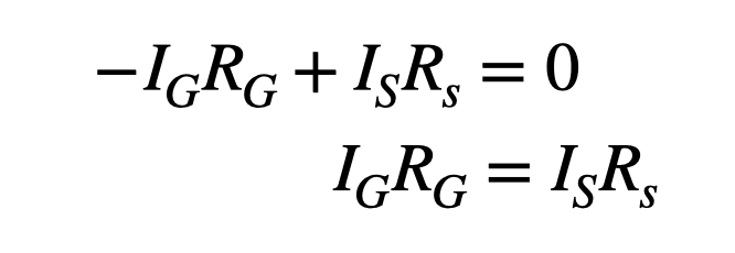
I know the values for I, I_G, and R_G but need to solve for I_s and R_s using two equations.
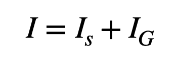
Through calculations, I found a shunt resistance of 0.22 Ω. This lower resistance allows more of the 200 mA current to flow through the shunt rather than the galvanometer.
To convert the galvanometer readings into mA, we see that if 200 mA corresponds to 5 GU (Galvanometer units), then each GU equals 40 mA. The new meter resistance, combining both resistors in parallel, calculates to:
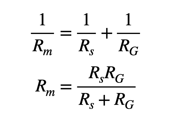
With this, I get a resistance of 0.21 Ω, which is crucial because when measuring a circuit with a 1-volt battery and a 100 Ω resistor, the expected current would be 10 mA. If the ammeter adds significant resistance, it affects the measurement accuracy.
For minimal resistance like 0.22 Ω, using a wire is ideal. For instance, a 30 gauge copper wire with a diameter of 0.25 mm can achieve this. Given copper's resistivity of 1.68 x 10^-8 Ωm, I can calculate the required length.
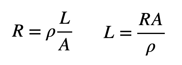
From my calculations, the wire length needed is approximately 0.64 meters. If that seems excessive, using a thinner wire or nichrome wire could also suffice.
Creating a Voltmeter
Next, I’ll adapt the galvanometer to function as a voltmeter. The principle here is to allow current to flow through the meter and determine the voltage difference across its terminals.
For the voltmeter, instead of a shunt resistor, I’ll incorporate a series resistor.
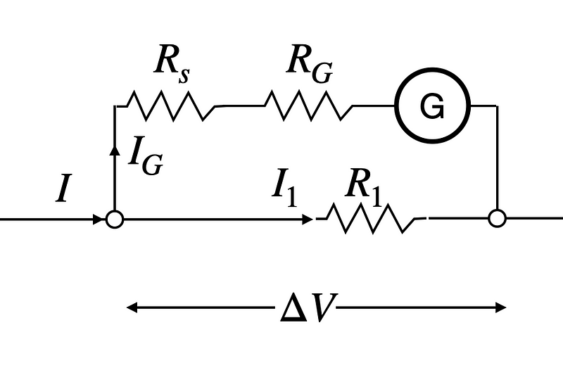
Now, with the series resistor (R_s) connected across a resistor R_1, I aim for the galvanometer to register a maximum voltage of 5 volts, equating each unit to 1 volt.
The required series resistance can be calculated based on the maximum current flowing through the galvanometer.
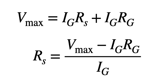
For a 5-volt maximum reading, a series resistance of 11.2 kΩ is necessary. This configuration results in a total resistance of 11.21 Ω. It's essential for an ammeter to have low resistance, whereas a voltmeter should have high resistance to minimize current draw when measuring voltage.
DIY Galvanometer Fun
As an interesting alternative, you can create a simple voltmeter/ammeter using a magnetic compass with wire wrapped around it.
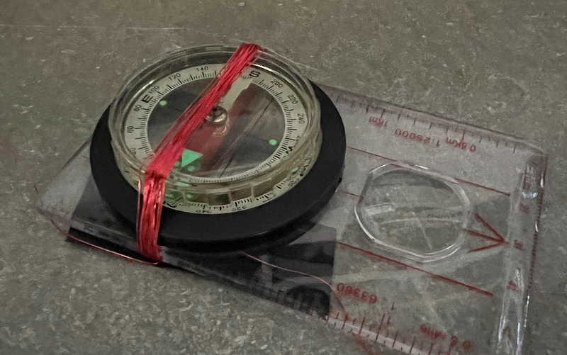
In this setup, electric current through the wire generates a magnetic field, causing the compass needle to align with the resultant magnetic field. While this compass-galvanometer is easy to build, it requires a larger current for noticeable deflection, and the scale is non-linear.
In conclusion, while crafting your voltmeter and ammeter may present challenges, the process is both educational and rewarding, offering hands-on insights into electrical principles.
The first video titled "How to Create a Simple Circuit with Voltmeter and Ammeter" provides a step-by-step guide for setting up your own circuit with these devices.
The second video, "DIY Simple Voltmeter / Ammeter With 5.5mm Connectors," illustrates how to create your own voltmeter and ammeter using easily accessible components.